• Skip to primary navigation
  • Skip to main content
Reduction LLC

Have a Question?1-585-329-9718

  • Home
  • Run/Dry Evaporators
    • Electric Models
    • Gas Models
    • Accessories
  • Free Wastewater Evaluation
  • Industries
  • Contact
You are here: Home / Run/Dry Evaporators / Accessories / Oil Water Separators
Oil Water Separators

Oil Water Separators

Description

A HIGH-EFFICIENCY OIL WATER SEPARATOR

• Reduces coalescing media failure • Reduces pretreatment needs
• Reduces post treatment needs
• Lowers total cost of ownership

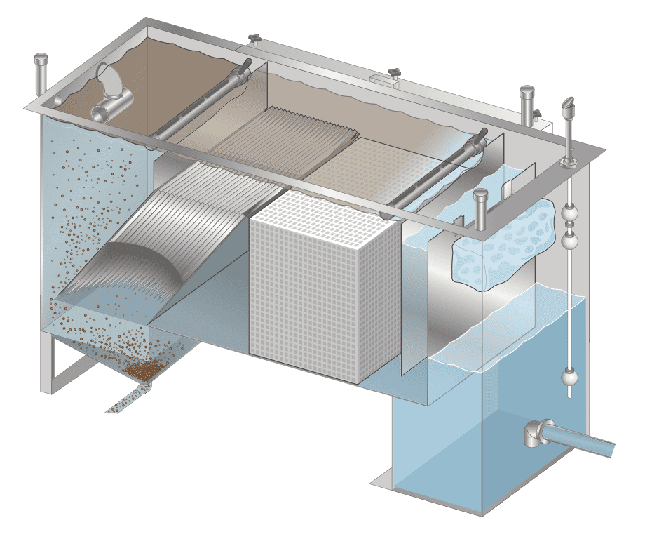
Clarification Separator is recommended for any application that has oil and a high concentration of settleable and suspended solids.

The Clarification Separator is a horizontal gravity flow pretreatment solution designed to separate settleable solids (specific gravity greater than water), suspended solids (specific gravity the same as water), and free and dispersed (non- emulsified) oil.

Units are built out of stainless steel or carbon steel. We offer several coating solutions for your specific application, such as brine water or frac water.

Our Clarification Separator, when used in conjunction with post treatment filtration, such as reverse osmosis (RO), dissolved air flotation (DAF) or electrocoagulation (EC), treats wastewater so it can be recycled or discharged.

This unit lowers the total cost of ownership of the entire water treatment system by:

  • preventing large amounts of solids from entering coalescing chamber, reducing coalescing media failure.
  • eliminating need of inefficient settling basins or frac tanks prior to treatment process.
  • decreasing amount of carry- over entering into post treatment process.

All Reduction LLC evaporators and accessories are free standing. Installation is plug and play for a fast and easy start up.

  • Single Hopper Units
  • Double Hopper Units
  • Separation
  • Applications

Single Hopper Units

Model BPD (BARRELS PER DAY) Inlet Outlet Dia. Width Height Length Clarifier Projected Plate (FT2) Separator Coalescing Media (FT3) Flow Rate (GPM) Sludge Volume (GAL) Capacity (GAL)
DRG-CS-10 342 2″ 2′ 4″ 4′ 10″ 7′ 0″ 40 4 10 27 300
DRG-CS-20 685 2″ 3′ 4″ 5′ 10″ 8′ 0″ 80 6 20 32 652
DRG-CS-30 1,028 2″ 3′ 4″ 5′ 10″ 9′ 2″ 120 12 30 45 645
DRG-CS-50 1,714 3″ 4′ 4″ 5′ 10″ 9′ 8″ 200 24 50 85 968
DRG-CS-75 2,571 3″ 4′ 4″ 7′ 10″  10′ 6″ 300 24 75 85 1,766
DRG-CS-100 3,428 4″ 5′ 4″ 7′ 10″ 11′ 0″ 400 30 100 107 1,931
DRG-CS-150 5,142 6″ 6′ 6″ 8′ 4″ 12′ 0″ 600 64 150 300 3,483

*Dimensions are approximate and may vary depending on your application.
Oil Removal of 20 Micron Based on Flow Rates Clarifier Projected Plate based on .25 gpm per sq. ft. Design Temperature 40° F (5° C)

Double Hopper Units


Model BPD (BARRELS PER DAY) Inlet Outlet Dia. Width Height Length Clarifier Projected Plate (FT2) Separator Coalescing Media (FT3) Flow Rate (GPM) Sludge Volume (GAL) Capacity (GAL)
DRG-CS-200 6,857 6″ 7′ 6″ 9′ 6″ 14′ 0″ 800 80 200 300 5,496
DRG-CS-250 8,571 8″ 8′ 6″ 10′ 6″ 15′ 0″ 1,000 96 250 350 6,986
DRG-CS-300 10,285 8″ 8′ 6″ 10′ 6″ 16′ 0″ 1,200 120 300 400 6,846
DRG-CS-350 12,000 8″ 8′ 6″ 10′ 6″ 18′ 0″ 1,400 144 350 425 7,633
DRG-CS-400 13,714 8″ 8′ 6″ 10′ 6″ 19′ 0″ 1,600 150 400 500 8,138
DRG-CS-450 15,428 8″ 8′ 6″ 10′ 6″ 20′ 0″ 1,800 168 450 525 8,612
DRG-CS-500 17,142 8″ 8′ 6″ 10′ 6″ 21′ 4″ 2,000 210 500 550 9,220
DRG-CS-550 18,857 8″ 8′ 6″ 10′ 6″ 22′ 6″ 2,200 210 550 675 9,765
DRG-CS-600 20,570 10″ 9′ 6″ 10′ 6″ 22′ 0″ 2,400 252 600 700 12,285
DRG-CS-700 24,000 10″ 10′ 6″ 11′ 6″ 25′ 0″ 2,800 280 700 750 15,440
DRG-CS-800 27,428 10″ 10′ 6″ 11′ 6″ 26′ 0″ 3,200 315 800 775 16,077
DRG-CS-900 30,850 12″ 10′ 6″ 11′ 6″ 27′ 0″ 3,600 350 900 800 16,717

*Dimensions are approximate and may vary depending on your application.
Oil Removal of 20 Micron Based on Flow Rates Clarifier Projected Plate based on .25 gpm per sq. ft. Design Temperature 40° F (5° C)

Separation

5 STAGES OF SEPARATION

  1. The free oil (150 micron in size or greater) is separated in the inlet quiescent zone. (Pipe skimmer provided to decant oil.)

  2. The settleable solids will flow downward into the hopper section for removal.

  3. The suspended solids and dispersed oil will flow upward through the inclined plates section, where most of the suspended solids will slide down the plates into the hopper (based on a design of .25 gpm per square foot of projected plate surface area).

  4. The remaining suspended solids and dispersed oil will flow into the separation compartment where the coalescing plates will separate the oil 30 micron or greater to the surface for removal and the remaining suspended solids will be captured in the coalescing plates. The amount of solids in the plates will determine the frequency of plate cleaning. (Pipe skimmer for removal of separated oil.)

  5. The flow of water will go over the overflow weir plate into the clean water compartment where ab- sorption bags will prevent any carryover from being discharged. (Optional float switch shown.)


Applications

OIL & GAS APPLICATIONS

  • Onshore and Offshore Drilling Operations
  • Oil Refineries
  • Flowback Water from
  • Hydraulic Fracturing
  • Produced Water
  • Waste Oil Processing Facilities
  • Frac Water

OTHER APPLICATIONS

  • Washing Applications
  • Industrial Applications
 
Reduction LLC
  • Home
  • Run/Dry Evaporators
  • Contact Us

1-585-329-9718120 Triple Diamond Blvd Unit H | N Venice, FL 34275

© 2015-2023, All rights reserved | Site by Industrial Webworks